http://www.shdesigns.org/lionchg.html


| Schematic (Adobe .pdf) | Description |
| lionchg.pdf | Original version, simple charger |
| lionchrg2.pdf. | An improved version with a charge monitor LED |
| lionchg3.pdf. | Programmable from 1-3 cells and 10 to 985 ma. |
The above schematics can be viewed in Adobe PDF here:(right-click on link and select "save link as" to save.)
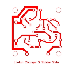
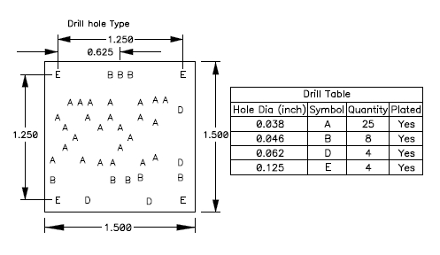
Update 9-27-2003: I have plot files for a PCB. They are available in gerber and pdf. The board is 1.5" square. The files can be found in a zip file here: Plots.zip
Kevin Austin provided another CAD file for the LED version in AutoCAD dwg format: li-chg.dwg
Updated: 04-28-2003 - changed U1 pinout numbering. CAD package used non-standard pin numbers. Modified symbol to use standard pin numbering.
Update 4-27-2004: The above programmable charger has been modified. It now sets multiple voltages without adjusting the pot each time.
How to modify the circuit for different size cells ![]()
The above circuit will charge any 2-cell * Li-Ion battery pack. Maximum current is about 650 milliamps. The circuit is designed for batteries of 900mah or higher. Note this circuit is NOT for Li-Metal batts (i.e. Duralites). Power source can be a 12v Gell cell (Power panel), or can be powered by a car's cigarette lighter. I use an old 12v DC wall transformer (800ma or more.) Radio shack sells a 12v/1amp wall DC adapter #273-1776 that will work. Supply does not need to be regulated. In fact my cheap supply outputs 17 volts with no load.
Note: Some people have commented that this circuit is not "Smart enough" to charge a Li-Ion battery properly. As long as you don't discharge the battery below about 3.0v per cell, this circuit follows the Panasonic recommendations exactly. Below 2.9v/cell, the batteries will need to be trickle charged (0.1 C) until they reach 3.0v/cell. Discharge below 2.3v/Cell will damage the battery. The circuit will not overcharge the battery. When the battery is fully charged, the current drops to zero (actually, the leakage current of the battery.) It will maintain the charged state forever. I have left cells on this charger for months.
When used in a flight pack with a ESC with a low-voltage cutoff, it will normally shut the motor off long before the low voltage limit is reached. And even then, the battery will "Self recover" back up a bit. Be sure to measure the pack with a voltmeter (no load) before charging. Trickle charge if needed. You can convert the above circuit to a trickle charger by using a switch to select 2 R1 values. A 10 ohm, 1/4 watt value in place of R1 will work as a trickle charger.
Notes:
- Do not charge batteries discharged below 2.9v/cell. If this occurs,use a trickle charge until 3v/cell is reached. (A standard wall charger for radio RX batteries should work.)
- Input voltage can be from 11-18v.
- Q1 (Q2) can be any general-purpose NPN transistor.
- All resistors are 1/4 watt except for R1, which is 1/2W or larger.
- C1/2 are any 0.1uf capacitors.
- The charge current can be monitored by a voltmeter across R1. Scale: 1Volt = 1 Amp.
- The new version includes an LED that will go off when the current drops below 20ma or so.
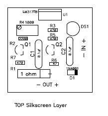
- The pinout of the LM317 is shown on the schematic. This pinout is defined by my CAD package and is not the same as the LM317 data sheet. Be sure to wire according to the schematic pin diagram.
- R6 sets the current that the LED turns off. This is about 10ma. Use 22 ohm for 25ma, 27ohm for 20ma, 33 ohm for 15ma. Currents are approximate as the tolerances in the transistor and diodes are not exact and may vary a bit with temperature.
Assembly:
The entire circuit can be constructed on a small perf board 1" square or so. U1 (LM317) must have a heat sink; a small piece of aluminium will do. There are many heat sinks available. The size of the heat sink depends on the input voltage and the battery capacity. Note: the case of U1 is connected to pin 3, so the heat sink must be isolated from any other parts of the circuit. An insulator (TO-220 type) can be used to isolate the case from the heat sink if needed (i.e. bolting U1 to the case as a heat sink.) U1 should not get too hot to touch.
Adjust R4 for 8.4V out with no load.
Parts: Radio Shack part numbers given. Improved version added parts in brackets ().
| Description | RS part # | |
| U1 | LM317T adj. regulator | 276-1778 |
| Q1 (Q2) | 2N2222A NPN trans. | 276-2009 |
| R1 | 1 ohm, 1/2 watt resistor (note 1) | 271-131 |
| R2 | 2200 ohm 1/4 w, 5% res | 271-1325 |
| R3 (R5,R7) | 470 ohm 1/4 watt, 5% res | 271-1317 |
| R4 | 1K trim Pot | 271-280 |
| C1,2 | 0.1uf/50v ceramic cap | 272-135 |
| Heat Sink | 276-1368 | |
| Mounting hardware (note 2) | 276-1373 | |
| (DS1) | LED (any will do) | |
| (R6) | 47 ohm resistor. | |
| (D1) | Any 1N400x diode. |
Notes:
1. RS part is 10 watt, only size they carry in 1 ohm.
2. Required if heat sink is yo be isolated (recommended.)
How it works:
Panasonic recommends charging at a constant current of 0.7C until 4.2V/cell is reached. Then constant voltage (CV) is to be used until current drops to 0.1C. At that time, the charging should stop. The circuit follows this recommendation exactly. However it does not turn off the charge. Testing has shown that the current drops to almost zero anyway.
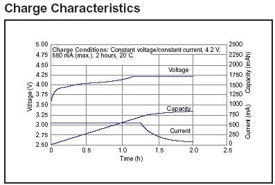
The circuit simplifies this by limiting the charge voltage to 8.4v. When the battery reaches 8.4v, it will no longer draw current. The charger is also current-limited. Below about 75% charge, the limit current is reached. After about 80% charge, the current decays toward 0. At about 95% charge the current drops to only a few milliamps. In theory, the battery will never finish the charge, the closer it gets, the less current it draws. If left on the charger for 2 hours or so it will reach near 100% charge. But, 95% can be reached in less than an hour in most cases (assumes discharged to 50% or so.) Panasonic's charge curve for their 830mah batts using this method is shown below:
U1 and resistors R2, R3 and R4 create a voltage regulator. This sets the termination voltage. U1 will try to maintain 1.25v across R3. The voltage divider created by R2-R4 multiply this voltage to get the desired 8.4v value.
Q1 and R1 set the current limit. The current drawn by the battery passes through R1. As the voltage across R1 approaches 0.65v, Q1 begins to turn on. Q1 then draws current from the voltage divider. This fools U1 into thinking the voltage is too high so it reduces the output.
C1 and C2 are used to reduce noise and guarantee that U1 does not become instable. Without them, U1 may oscillate.
=================================
Modifying the design for different cell sizes:
R1 sets the current limit. Panasonic says to use 0.7C max current. 1 ohm works for 900mah or so. You can adjust R1 for a pack of any size. As long as the current is smaller than 0.7C, then there will be no damage to the battery. To adjust R1 for a different pack size:
| Design Parameters | Value | Example for 600 mAh |
| Max Current (amps) | 0.7 * C | 0.600 * 0.7 = 420ma (0.420 amps) |
| R1 | 0.65/Max Current | 0.65 / 0.420 = 1.55 ohms |
| R1 Power Dissipation | Max Current * 0.65 | 0.420 * 0.65 = 0.273 watts |
You can not easily buy a 1.55 ohm resistor. So either use one that is close or make one by paralleling resistors. If you connect N resistors in parallel, the resistance divides by N and the power multiplies by N. So to try to get 1.55 we can use three 4.7 ohm, 1/4 watt resistors in parallel:
R=4.7/3 = 1.567 ohms - Close enough
P= 0.25 *3 = 0.75watts
Try to make a R1 value that is as close as possible or larger.
Here's some calculated values for R1:
| Pack Size | Calculated R1 | Parallel R to use | Result | Max Current |
| 800mah | 1.16 ohm | 4.7 ohm * 4 | 1.175 ohm | 553ma |
| 1200mah | 0.774 ohm | 2.2 ohm *3 | 0.773 ohm | 886 ma |
| 600ma | 1.548 | 4.7 ohm *3 | 1.567 | 415 ma |
You can parallel different resistors to get the desired current. Here's a table of current per resistor:
| Resistor Value | Current | Power Dissipated |
| 1.0 ohms | 650 ma | 0.423w, use 1/2w |
| 1.5 ohms | 433 ma | 0.282w, use 1/2w |
| 2.2 ohms | 295 ma | 0.192w, use 1/4w |
| 2.7 ohms | 241 ma | 0.157w, use 1/4w |
| 3.3 ohms | 197 ma | 0.128w, use 1/4w |
| 4.7 ohms | 138 ma | 0.090w, use 1/4w |
| 6.8 ohms | 125 ma | 0.813w, use 1/4w |
| 10 ohms | 65 ma | 0.042w, use 1/4w |
So if you wanted about 500ma max you could use a 2.2 and 3.3 ohm resistor in parallel for 295+197=492ma, close enough. 1/4 watt resistors are all that are needed for paralleled operation if the value is greater than 1.69 ohms.
Note: the LM317 is limited to 1.5 amps. A LM350 can be used for up to 3 amps.
Modify the number of cells:
R2 sets the voltage range. To change the number of cells, change R2 and adjust voltage as shown below:
| # Cells | R2 | Voltage | Min. Supply Voltage |
| 1 | 1K ohm | 4.2 | 6v |
| 2 | 2.2K ohm | 8.4 | 12v |
| 3 | 3.9K ohm | 12.6 | 16v |
| 4 | 5.6K ohm | 16.8 | 20v |
| 5 | 7.5K ohm | 21 | 24 |
Increasing charge speed:
Panasonic specifies stopping charge at 4.2v/cell. But they say 4.3v/cell is the maximum allowed. For 2-cells that is 8.4 and 8.6v respectively. As the cell approaches 4.2v/cell the current drops significantly. I set mine for 4.25v/cell (8.5v.) This is under the maximum and reduced the charge time a bit. The laptop I took the cells from actually charged to 8.6v. So, 8.5 is a good value for better charge time. But don't leave the batts on this charger for more than a few hours. The improved charger design can be used. This will turn off the LED when the batteries are charged fully.
Change the LED turn off current:
R6 sets the current that the LED turns off. This is about 10ma. Use 22 ohm for 25ma, 27ohm for 20ma, 33 ohm for 15ma. Currents are approximate as the tolerances in the transistor and diodes are not exact and may vary a bit with temperature.